

Powermatic 3520 Switch Replacement
All too frequently it is reported on turning forums that another ON/OFF switch on
a Powermatic lathe has bitten the dust. I have not a clue why this switch is prone
to failure, but fail they do, or at least some do. On the other hand, some turners
have ope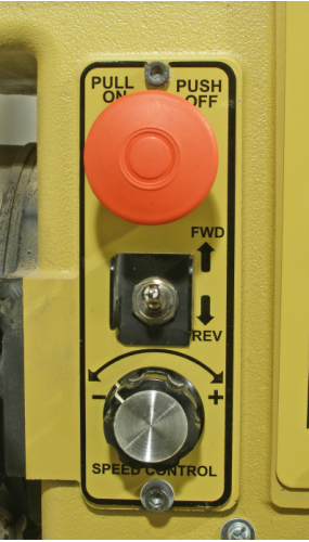 rated one for years with no problems at all. It’s the luck of the draw, or
so it seems.
rated one for years with no problems at all. It’s the luck of the draw, or
so it seems.
This article explains how to remove and replace the switch. Unless you are familiar with switches of this type, it can be a bit of a puzzle. And, yes, this article stems from my recent experience of having to replace the one on my lathe.
Description of the Unit
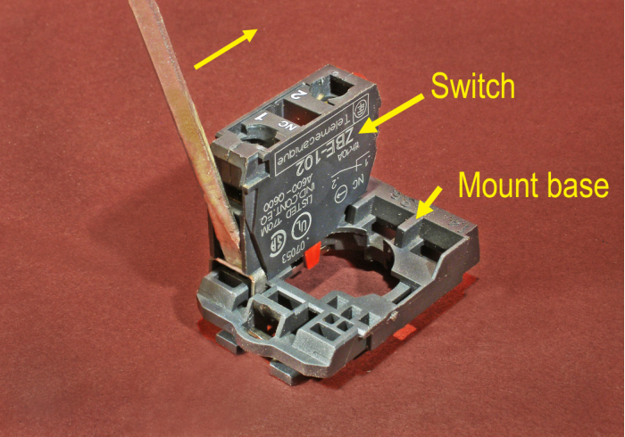
The unit consists of three parts: the mushroom actuator (the knob part), the mount base (or mounting collar), and the switch. To remove the unit from the panel, the actuator and mount base must be separated.
The actuator and mount base are held together by a rectangu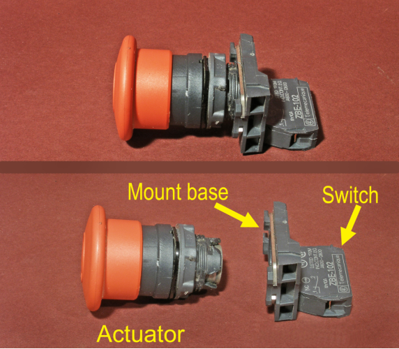 lar metal clip that engages
two slots on the actuator assembly. The switch is held on the mount base by a spring-
lar metal clip that engages
two slots on the actuator assembly. The switch is held on the mount base by a spring-
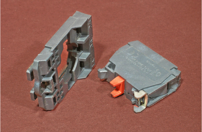
The metal clip can be sprung apart enough to disengage the slot by inserting a small
flat-
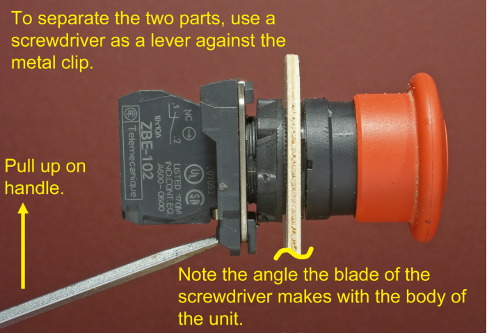
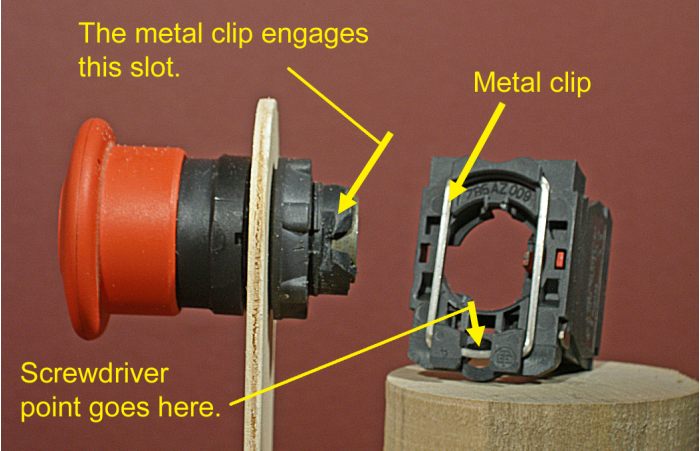
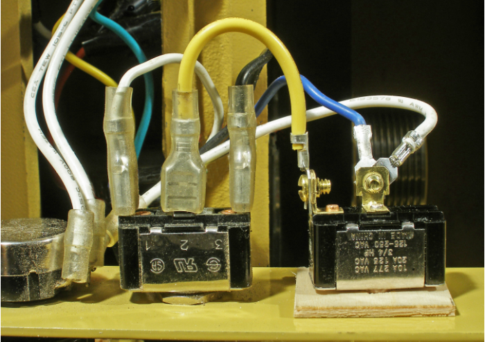
Here are two more photos that show more detail:

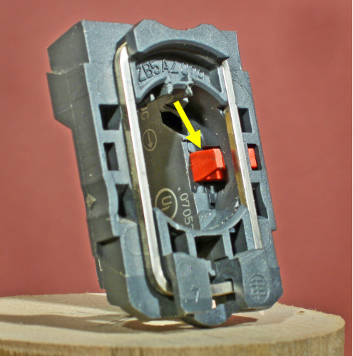
The following photos show how the switch is removed from the mount base by using
a small screwdriver to release the spring-
The Fix is Quick.
When the unit fails to function, it is almost a certainty that the fault lies with the switch itself and not the actuator or mount base. Therefore, you only have to replace the switch, which is quick and easy to do. Here’s the procedure.
First, obviously, remove all electrical power from the lathe.
Use a 5/32” Allen wrench to remove the two cap screws that holds the control panel in place. Carefully pull the panel out of the frame far enough to give access to the switch.
Loosen the screws on the switch block that hold the connectors. Pull upward at a small angle to remove the connectors, which do not insert straight in.
Slide a small, flat-
Install the new switch in the mount base by either pressing it in, or, more elegantly,
use the screwdriver to open the spring-
Reinstall the electrical connectors, then re-
The Procedure for Replacing the Entire Unit
If for whatever reason you need to replace the entire unit, here’s the procedure, in considerable detail.
First, remove all electrical power from the lathe.
Use a 5/32” Allen wrench to remove the two cap screws that holds the control panel in place. Carefully pull the panel out of the frame.
Loosen the screws on the switch block that hold the connectors. Pull upward at a small angle to remove the connectors.
Remove the mount base and switch from the actuator assembly.
Use a pair of channel-
Install the new actuator assembly. Orient it so the slots for the metal clip are on the sides as opposed to being on the top and bottom. Install the nut and tighten moderately.
Install the new switch on the new mount base.
Install the new mount base (with switch attached) on the actuator. It’s easier if you use the screwdriver to spring the metal clip, but you can do it by just pushing it onto the actuator body.
Re-
Replace the panel and restore power to the lathe. And that’s it.
A Stopgap Repair
Switches always seem to fail at the worst possible moment, when you’re in the middle of a project and pushing a deadline. It’s an unwritten law of the universe.
Here’s a way to get your lathe going again with a temporary fix that will allow you to use your lathe while you wait for parts to arrive. The idea is to install a toggle switch, obtained locally, in place of the big red knob. It may not be as pretty, but it will work.
Go shopping (at a big-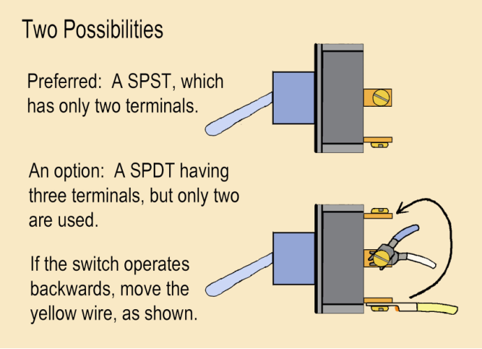 inals (single-
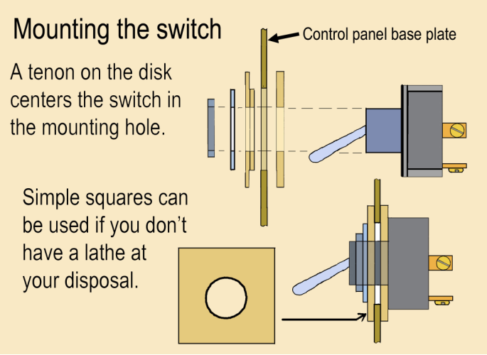
Remove the big red knob and mount the toggle switch in the 7/8” hole. Two thin disks (or squares) are required, with a hole at their centers for the toggle switch mounting stud to pass through. The mounting nut of the toggle switch will tighten against the disks and pull them up tight against the periphery of the hole. Details for making the disks are given below.
Install the electrical connectors on the screw terminals, replace the panel, and you should be back in business.
The operating lever (the actual toggle) on some toggle switches is rather short and
takes a significant force to operate. In an emergency situation, it should be easy
to find and easy to “flip.”
emergency situation, it should be easy
to find and easy to “flip.”
A short piece of plastic or vinyl tube slipped over the toggle makes it much easier to operate as well as making it easier to “hit” in an emergency. Also, the tube will bend and avoid damage to the switch if you accidentally brush against it or hit it too hard in a stressful moment.
One little note: If you installed a three-
How to turn the disks for mounting the toggle switch.
Begin by laying out two 1.25” square blanks on a sheet of 1/8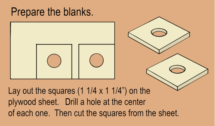 ” plywood obtained from
a hobby shop, or use whatever material you have at hand that is a workable thickness.
Drill a hole at the center of each blank (typically 15/32” diameter) for the threaded
section of the toggle switch to pass through. Then cut the blanks from the sheet.
” plywood obtained from
a hobby shop, or use whatever material you have at hand that is a workable thickness.
Drill a hole at the center of each blank (typically 15/32” diameter) for the threaded
section of the toggle switch to pass through. Then cut the blanks from the sheet.
Here’s a bit of a catch: if your lathe is inoperative, how can you turn the disks? Perhaps you have another lathe, but if you don’t, simply use the square blanks as you cut them from the sheet. It won’t be quite as neat and the switch will not automatically center in the mounting hole, but it will get you up and running again.
Assuming you have a working lathe at your disposal, the next step is to make a mandrel
for turning the squares into disks, one 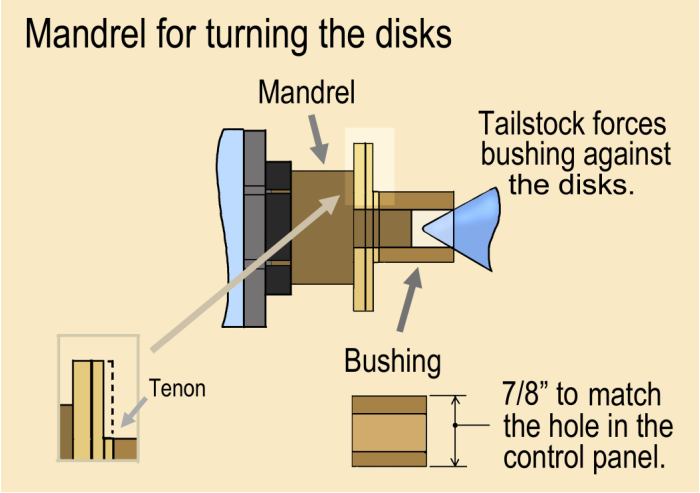 of which will have a tenon. A bushing is
used to press the blanks against the shoulder on the mandrel to lock them in place
for turning.
of which will have a tenon. A bushing is
used to press the blanks against the shoulder on the mandrel to lock them in place
for turning.
It’s convenient to make the bushing first. Install a short piece of spindle stock in a scroll chuck. True it up and face off the end. Use the same drill bit you used earlier to drill a hole about 1.25” deep into the blank.
Then, turn the outside diameter down to 7/8” so it will just f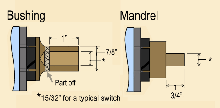 it into the hole in
the control panel. Check the fit, just to be sure. Finally, cut the bushing free
with a parting tool.
it into the hole in
the control panel. Check the fit, just to be sure. Finally, cut the bushing free
with a parting tool.
The reason for carefully sizing the outside diameter of the bushing is that it will be used to establish the diameter of the narrow tenon formed on one of the disks. This avoids the difficulty of trying to measure the diameter of a tenon that may be only 1/16” wide.
Turn the mandrel from another piece of spindle stock. Make the small-
Turn the disks. Place the two blanks on the mandrel and use the bushing and tailstock to hold them in place. Turn them round, then cut a narrow tenon (1/16” or less) on one of the disks. Make the tenon diameter 7/8”, the same size as the bushing.
A brilliant idea would be to buy the toggle switch and make the mounting disks ahead of time, to have it on hand and ready to make the stopgap repair quickly if the need ever arises. Better yet, you could go ahead and buy a replacement switch ... but that’s asking a bit much.
Part Numbers
The parts of the assembly, namely the actuator, mount base, and switch, are standard industrial components and are available from many sources. A web search for these part numbers will turn up a lot of hits.
Telemecanique ...
Red push-
(Emphasis: push-
Mount base, or mounting collar: ZB5AZ009
Switch, normally closed contacts: ZBE-
Thanks to Rob Wallace whose 5/8/2013 post to the turning messageboard on WoodCentral (www.woodcentral.com) steered me in the right direction in my time of need. Very helpful!