

PM 3520 Control Circuitry
Part 1: Description
I recently had the opportunity to observe as a friend of mine removed and re-
And yes, the inverter can, in most cases, be repaired by a qualified person. The parts that usually fail are the electrolytic capacitors in the switching power supply. These are inexpensive and are easily replaced. In such a case, you don’t have to dig into the “complicated stuff” that forms the heart of the drive.
I took advantage of the situation and decided to see if I could unravel some of the mysteries of the control circuitry. As it turns out, it is rather simple. A description of the circuit follows.
The following article, Part 2, gives a procedure for troubleshooting the control circuitry. Part 3 is a short extension of Part 2 and gives suggestions relating to removing the inverter from the lathe, if such should become necessary.
Description of the Control Circuit
The circuitry is located behind the small panel on which the big red knob is mounted. It consists of the Start/Stop switch (the big red knob), the Forward/Reverse switch, and the Speed Control.


Only five wires run from the inverter to the control panel:
Blue – Ground for the control circuit
Yellow – Power supply, +10 VDC
Green – Speed control, voltage varies from 0 to 10V
White – Lathe runs in forward direction when this wire is grounded.
Black – Lathe runs in reverse when this wire is grounded.


Two other wires are in the bundle that comes from the inverter. One is red and the
other is gray or an off white. Show these some respect because they carr y 240 VAC
to power the RPM display. Normally you don’t have to mess with these, but if a wire
nut should come loose and expose either one of these, turn off the power and make
the repair.
y 240 VAC
to power the RPM display. Normally you don’t have to mess with these, but if a wire
nut should come loose and expose either one of these, turn off the power and make
the repair.
Wiring Diagram for the Control Circuit
The circuitry can be divided into two sectio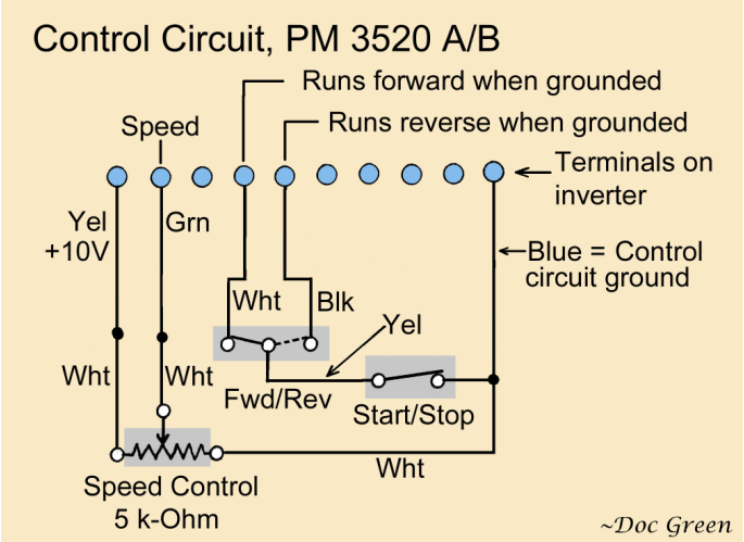 ns. One section turns the lathe ON and
OFF and determines whether it will run forward or in reverse. The circuitry includes
the Start/Stop switch and the Fwd/Rev switch. In this article, I refer to this section
as the start/stop/direction circuitry.
ns. One section turns the lathe ON and
OFF and determines whether it will run forward or in reverse. The circuitry includes
the Start/Stop switch and the Fwd/Rev switch. In this article, I refer to this section
as the start/stop/direction circuitry.
The other sets the RPM. This circuit consists of the speed control knob and the 10-
The inverter has two terminals (4th and 5th from the left in the row of control terminals) that control when the lathe will be running and in which direction. A white wire connects to the 4th terminal and a black wire connects to the 5th. These terminals are “active low.” This means that to activate the terminal, you connect it to ground. To deactivate the terminal, you leave it open, which is the equivalent of not connecting it to anything at all.
Consider terminal 4, the one with the white wire. If this terminal is grounded, the lathe will turn ON and run in the forward direction. If you remove the ground, the lathe will stop.
Similar thing for 5, the one with the black wire. If this terminal is grounded, the lathe will turn ON and run in reverse. If you remove the ground, the lathe will stop.
How it works:
To see how the circuit works, let’s trace the path from terminal 4 and terminal 5 through the Fwd/Rev and Start/Stop switches to ground. These terminals connect to the end terminals of the Fwd/Rev switch via a white and a black wire, respectively.
The Fwd/Rev switch is a single- inal will be connected to one of the end terminals. Exactly which
one depends on the position of the toggle. Flip the toggle, and the connection will
switch over to the other end.
inal will be connected to one of the end terminals. Exactly which
one depends on the position of the toggle. Flip the toggle, and the connection will
switch over to the other end.
Therefore, only one of terminals 4 and 5 can reach ground at a given time. But whether the path to ground is actually completed depends on the Start/Stop switch. Note that the center terminal of the Fwd/Rev switch connects through a prominent yellow wire to one side of the Start/Stop switch (big red knob).
For the path through the Start/Stop switch to be complete and reach the blue ground wire, the big red knob must be pulled out, which of course is what you do to turn the lathe ON. This completes the path to ground and one of the terminals 4 or 5 will then be grounded. Which one depends on the position of the Fwd/Rev switch.
If the big red knob is NOT pulled out (lathe not turned ON), neither terminal #4 or #5 will be grounded, and the lathe will be OFF.
What voltage appears at terminals 4 and 5 when one or both are not grounded and forced to zero volts? The circuitry inside the inverter causes an ungrounded terminal to “pull up” to a fairly high voltage. How high? I measured 16.6 V on my inverter. So, making the connection to ground drops the voltage at the terminal from 16.6 V to 0 V, and this activates the terminal.
The Speed Control
Terminal 2 (second from left in the row of terminals) is the speed control terminal. The inverter will run the motor at an RPM directly proportional to the voltage applied to this terminal. Increase the voltage and the RPM will increase.
There are limits, of course. When the applied voltage drops below about 0.3 V, the lathe will stop. When the applied voltage is about 10 V, the motor will be driven at full speed. If the connection to the speed control terminal is broken, i.e., the terminal becomes open, the lathe will not run.
The speed control circuit is a circuit that can deliver a variable DC voltage to
terminal 2. Specifically, it is a type of variable resistor known as a potentiometer,
or just a “pot.” The voltage is varied by turning the speed-


A pot consists of a resistance element connected between two of its three terminals. The third terminal connects to a sliding contact (called the slider) that can be moved along the resistance element. The knob moves the sliding contact.
In the simple voltage-
The sliding contact samples the voltage where it is positioned (by the knob) on the
resistance element. If it happens to be exactly at the half- will pick
up a voltage of 5 V. If it is moved closer to the 10 V end of the resistance element,
it will pick up a higher voltage, perhaps 8 V. Likewise, moving it toward the ground
connection causes it to pick up a smaller voltage.
will pick
up a voltage of 5 V. If it is moved closer to the 10 V end of the resistance element,
it will pick up a higher voltage, perhaps 8 V. Likewise, moving it toward the ground
connection causes it to pick up a smaller voltage.
The inverter supplies the DC voltage of 10 V to one side of the pot via the yellow wire connected to terminal #1. The other side of the pot connects to ground through the blue ground wire that goes to terminal 10. The output voltage from the sliding contact goes to the speed control terminal (2) through the green wire. (The wires connected directly to the pot are all white, but they are spliced to the yellow, green, and blue wires.)
Power Circuitry
While we’re here, let’s take a quick look at the wiring diagram for the power circuitry. It is quite simple even though at first glance, it will appear quite the opposite.
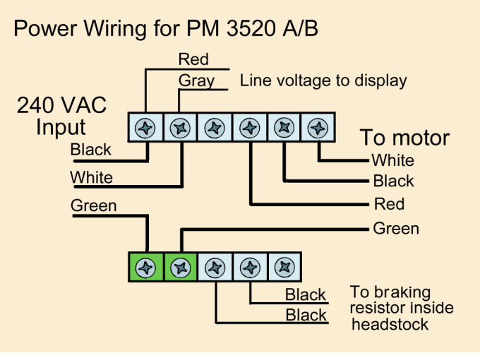

Input power is delivered to the unit by the line cord which has two “live” conductors and a ground. The live conductors are black and white; the ground wire is green.
Because the motor is a three-
The RPM display gets its power (240 VAC) from the two terminals on the inverter where the black and white wires of the line cord attach. Otherwise, the display is completely independent of the inverter.
The display will light up when input power is applied to the inverter, even if the inverter itself is dead. Conversly, if the display is lit up, you can be sure that input power is being supplied to the inverter.
The Braking Resistor
A large bowl blank spinning at a high RPM will contain a lot of energy. This energy must be dissipated in some manner when the lathe is turned OFF, and the faster the energy is removed, the more quickly the spinning blank will slow down and stop.
When the lathe is turned OFF, the inverter briefly changes the function of the motor to that of a generator. The output of the generator is connected to the braking resistor where the energy is converted to heat. The spinning blank will be slowed down as the energy is removed.
The resistor is mounted inside the case of the headstock. Two wires run from the
inverter to the resistor. Fortunately, if you have to send the inverter out for repairs,
you do not have to send the resistor with it. Therefore, you do not have to worry
about removing or re-